| |
 |
| CONTROL AND RELAY CABINETS TYPE KRO |
| |
| By integrating the secondary scheme subsystems,
the advantages of static design and modular construction have resulted in
standard solutions of protective and control functions, i.e. into factory
wired and tested units for protection, automation, control, signalling,
measurement, DC and AC auxiliary supply in associated feeders, electrical
interlockings and cable marshalling -in a single standard product -the Control
and Relay Cabinet KRO which represents the entire segment of the electric
control room of the plant. |
| |
|
|
| |
|
These self-contained units include thus all subsystems of secondary schemes
(including all preparations for remote control). The entirety of the plant
control room is obtained by simply composing these "sandwiches".
Both physical and electrical integration has been achieved for: control
board, indication panel, measurements, relay panels, DC and AC auxiliary
supply and cable marshalling for remote control.
This novel approach to the design and construction of secondary equipment
subsystems saves on an important part of the work - the electrical design
(operating diagrams have become the component part of KRO cabinets -only
cable connection diagrams have to be made). The required space in the
electrical control room and the time of installation, testing and putting
into operation on the site have been minimized.
Any future transfer to an unattended substation within the remote controlled
system will require minimum equipment and work.
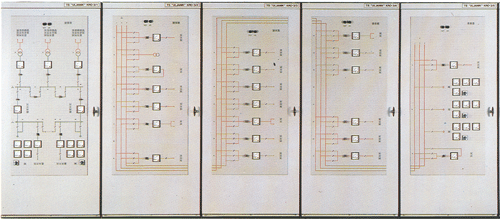
The cabinet door in mosaic technique bears the mimic diagram with control
elements, indicators and annunciation display elements. Each unit is an
electrically and physically self-contained whole. The continuity of mimic
diagrams is accomplished by the simple arrangement of cabinets in rows.
The front, supporting plate in the cabinet interior bears the surface
mounted elements of DC and AC auxiliary supply of associated feeders.
The supporting frame (swing-out or fixed type, depending on the method
of external wiring) bears, in a vertical arrangement, modular protective
subsystem racks and annunciation of the associated feeders (following
the single-pole diagram on cabinet door) including the functions of electrical
interlocking and preparation for remote control.
|
| |
|
Relay Cabinets RO
In cases where modular protective systems are employed
as a design replacement for conventional relay panels, relay cabinets
type RO are available.

|
Protective Relays in Individual Cases MZK
Modular construction of the system permits to taylor "per feeder"
segments as required. If a distributed arrangement of the secondary schemes
in medium voltage cubicles, i.e. a distributed arrangement of individual
functions is required, it is possible to install separate cases as a partition
in the cabinets. All the advantages of the modular system come to full
expression: electromechanical self-dependence of the protected feeder,
flush or surface mounted case with conventional screw type terminals and
lead sealing protective cover as required. The degree of protection is
IP42 as standard (to IEC 144), up to IP54 upon request.
Such standard solutions are available to our standards (including the
associated operating and wiring diagrams). If you face or will be facing
an engineering problem we are ready to solve it with you and create optimum
solutions for an existing or future construction phase. All we need is
a well-defined single-pole diagram of your substation. The best technical
and cost-effective solution will then be selected in close collaboration
with you.
Modular Protective System Power Supply
Cabinets are powered from a station battery of 220 V DC,
110 V DC, 48 V DC or upon request via a DC to DC inverter which supplies
output power of ± 24 V DC for electronics and provides galvanic isolation
from battery circuits. The applied inverter unit has a regulated, overvoltage
protected output, reverse polarity protected input and short circuit protected
input and output thus eliminating a great deal of failures often encountered
in the DC auxiliary supply circuits.
Mechanical Construction
Cabinets are supplied with swing-out frame (wiring accessible
from cabinet front by swinging out the hinged frame) or as a free standing
structure (accessible from cabinet front or rear side).
|
| Depending on the specific requirements, it
is possible to obtain a clear and compact (and low space requiring) arrangement
with all the advantages of a factory wired and functionally tested modular
protective system. |
| |
| Wiring methods |
| |
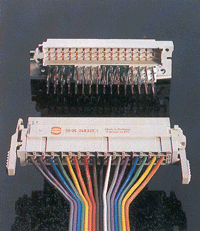
The connection between modules and the 19"
plug-in rack is made via standard connectors with the plug connector arranged
on the module and the socket connector on the mating position in the rack.
The connection from that point to the "designer's block, is made either
directly or via a plug and socket connector.
The plug and socket connector (crimping wiring technology is used on the
socket side) which receives all connections toward the external world, makes
the entrire 19" rack mechanically and electrically exchangeable. After
the plug and socket connector is disconnected and the high current capacity
connector withdrawn, the entire rack ("feeder") is electrically
and mechanically isolated from the plant, i.e.from the cabinet terminal
block; this canbe done while the plant is energized without disturbing the
operation of other serial devices/relays on the same core of current measuring
transformers. |
| |
 |
| |
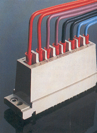
| An important feature of the system hardware
is the connection method of current modules on the rack and on the cabinet
terminal block. The connection toward the external world -the secondaries
of current measuring transformers is made via a special 8-pole high current
capacity connector. Upon withdrawal of current modules, the current connector
short-circuits the secondaries of the current measuring transformers (a
detailed description of this can be found in the catalogues).
|
| |
| Module combination |
| |
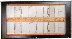
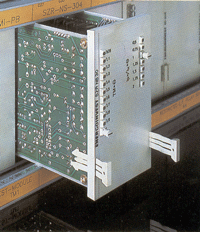
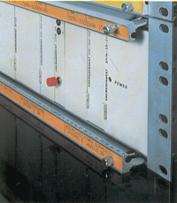
| The individual modules comprising the i functional
subsystems are plugged into racks (wired manually or by a computer controlled
machine). They are secured by lead sealing locking rails bearing module
identification tags (the employed symbols are from the operating diagrams). |
| |
 |
| This modular approach permits the composing
of individual relays and their combinations into subsystems and systems
of protection and automation; the same approach appears with the installation
of modules into individual housings and/or complete relay cabinets.
|