| |
DZR-EP, DZR2-EP

|

|
| DIGITAL IMPEDANCE PROTECTION |
| |
| Digital impedance protection of type DZR-EP,
DZR2-EP is a member of the device family named EuroProt. This short description
contains special data of this type. General and common features of EuroProt
family can be found in the EuroProt system information sheet. Accordingly
it is proposed to study both this short description and the system information
sheet, in order to get a clear picture of this protection. |
| |
|
| |
| Application field |
| |
The DZR-EP type digital three phase under-impedance
protection can be used as short-circuit protection in not grounded (isolated
or compensated) networks, and in grounded networks, if the minimal short-circuit
current and the maximal load current are at the same level, and therefore
the selective protection needs impedance measurement instead of overcurrent
protection. The protection is provided with offset circle characteristics,
which are suitable to solve special protection tasks as well.
The frequent applications of DZR-EP under-impedance protection are: the
reserve protection for generators in case of short-circuits inside the zone
of the differential protection, main protection of medium voltage bus-bars
of 120 kV/medium voltage transformers, reserve protection for short-circuits
inside the zone of transformer differential protection and for short-circuits
at the first section of the feeders.
The application of this protection is not advised, if directionality is
required, i.e. difference must me made between short-circuits in front of
and behind the protection. For these location the DKTVA-EP type distance
protection for medium voltage networks is developed. |
| |
| Main features |
| |
|
Under-impedance function:
- two stages of three phase under-impedance functions (Z<<, Z<)
with individual time delay
- the offset of the circle characteristics ( compaunding) can be set
for both stages independently
- 3 point measuring principle, not sensitive for current transformer
saturation
- shortest operating time: 25 � 5 ms
Overcurrent function:
- two stages of three phase overcurrent functions (I>>, I>)
with individual time delay
- for the overcurrent stages can individually be selected:
- trip circuit supervision in each phases
- always enabled
- enabled only if the MCB-s in the voltage measuring trip, and the
impedance stages are disabled
Software characteristics:
- built-in self-supervision functions
- event 1og storing 50 events, and digital event sequence recorder with
1 ms time resolution, recording maximum 300 events
- analog event log with current and voltage data
- intelligent digital function matrix
- two additional timers (T1 and T2) for free application in connection
with the matrix
- the rows of the matrix (relay-functions) can be set for latching
Hardware characteristics:
- numerical design, with own AID converter, digital signal processor
(DSP) and separate main processor
- 8 opto-coupler inputs
- 16 output relays
- the type of contacts (NO, NC) can be selected individually when ordering
Communication:
- 2x16 character LCD display for setting, message display and display
of recorded events
- on line screen on external PC for easier commissioning
- external communication connection can be set for RS 232 or fibre optic
cable
- optional interface modules for SCADA connection
- the parameters can be saved and downloaded
- real-time clock with battery-fed RAM, (can be synchronised from external
PC via fibre optic cable, from the SCADA system or via opto-coupler
input
|
| Working principle |
| |
The DZR-EP protection is a microprocessor controlled
system, so its functions and their variations are based on software.
The device contains several 87C196 type 16 bit micro-controller and a DSP
performing digital signal processing. The program is stored in EPROM, the
message text for the display is stored in EPROM as well. The parameter setting
is loaded in EEPROM. Events are recorded in battery supplied RAM. The man-machine
interface consists of a keyboard with six push-buttons, above it the two
row, 2x16 character LCD display, seven LEDs and two SW pushbuttons. With
auxiliary PC and with the handling program a device can easier be operated.
The analog current and voltage inputs are connected via inductive internal
measuring transformers and low-pass filters to the multiplexer then to the
AID converter, where all current and voltage signals are sampled in every
0,5 ms. The sampled values of the 16 bit AID converter are passed via high
speed CAN bus to the digital signal processors (DSP), which perform arithmetic
operation with high speed. The outputs of the DSP are the processed and
evaluated measurements, as "started" signals of the relay functions,
which are sent to the CPU. The timers and logic functions are performed
here. The central processor communicates via parallel bus with the opto-coupler
inputs and with the relay drivers.
The under-impedance protection function is in all three phases a two stage
impedance relay, and there is additionally a two stage overcurrent relay
as well. Each stages have individual timers. Each stage contains 3-3 parallel
impedance functions. Their operations is enabled by overcurrent relays with
0,2xIn fix setting. The staring caused by the highest phase current enables
the operation of both impedance stage in all three phases. The measurements
is disabled by the trip of midget CB in the voltage transformer secondary
circuit with selectable NO or NC contacts.
The two overcurrent functions contain RMS measurements. The delay of both
stages can be set independently. It can be selected by parameter setting
if it is always enabled or enabled only in case of tripping the midget CB,
causing the disabling of the impedance functions.
In case of DZR designed for not solidly grounded networks the impedance
measurements are performed according to the formula for the three phases
URS/2IR, UST/2IS and UTR/2IT.
The impedance setting is the positive sequence impedance of the line. In
case of two-phase short-circuits the explanation is drawn on Fig. 1.
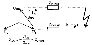
Figure 1.
In case of 3 phase short-circuits the impedance relays measure �3/2
times less values, they "over-reach" .The operating distance
of the function in case of 3 phase short-circuit is 2/�3=1,15
times greater, than that of 2 phase short-circuits. For the explanation
see Fig. 2.
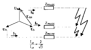
Figure 2.
In the DZR2 version for solidly grounded networks in case of earth faults
the phase voltage is divided by the phase current compounded with the
zero sequence current, and they calculate the positive sequence impedance
proportional to the distance.
The setting of the impedance function is made according to the characteristics
shown in Fig. 3.
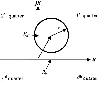
Figure 3.
|
| Technical data |
| |
Rated secondary current, In
|
1 A or 5 A |
| Rated secondary voltage (line), Un |
100 V or 200 V |
| Rated frequency |
50 Hz or 60 Hz |
Overload capacity, voltage circuit thermal, continuous
current circuit thermal, continuous
1 s |
2xUn/�3
4xIn
100xIn (In=1 A), 50xIn (In=5 A) |
| Dynamic current limit |
100xIn |
Accuracy, impedance relays (above 50% In)
Accuracy, current relays (above 50% In)
Accuracy, timers
|
� 5%
� 2%
� 3 ms (steps 10 ms)
� 12 ms (steps 1 s) |
| Reset ratio, current relays |
95% |
| Output relay contacts |
12 pcs |
| Type of contacts (NC, NO) |
1 NC, 11 NO (or as requested) |
Output contacts, electrical
data:
rated switching voltage
continuous load current
making current
DC breaking capability at 220 V,
at pure conductive load
at load ofL/R = 40 ms
option at load of L/R = 40 ms |
250 V
8 A
16 A
0,25 A
0,14 A
4 A |
Auxiliary DC voltage (the same supply unit)
voltage tolerance
|
220 V or 110 V
88 V to 310 V |
| Permissible ambient temperature |
0o to 50o C |
| Insulation test (IEC 255) |
2 kV, 50 Hz
5 kV, 1.2/50 �s |
| Disturbance test (IEC 255) |
2.5 kV, 1 MHz |
| Electrostatic discharge (ESD; IEC 801-2) |
8 kV |
| Burst test, (IEC 801-4) |
2 kV |
| Setting ranges |
| Impedance function second stage |
center of the characteristic (real axis),
Z<Ro(*10*Cu*Ci) |
0-10000 mOhm, step 10 mOhm |
center of the characteristic (imaginary axis),
Z<Xo(*10*Cu*Ci) |
0-10000 mOhm, step 10 mOhm |
radius of the characteristics,
Z<r(*10*Cu*Ci) |
0-10000 mOhm, step 10 mOhm |
| setting of the quarters, Z<RoXo position |
1-4, step 1 |
| Impedance function first stage |
center of the characteristic (real axis),
Z<<Ro(*10*Cu*Ci) |
0-10000 mOhm, step 10 mOhm |
center of the characteristic (imaginary axis),
Z<<Xo(*10*Cu*Ci) |
0-10000 mOhm, step 10 mOhm |
radius of the characteristics,
Z<<r(*10*Cu*Ci) |
0-10000 mOhm, step 10 mOhm |
| setting of the quarters, Z<RoXo position |
1-4, step 1 |
Remarks: The values of the constants in
the formulas above:
Cu=1, Un=100 V Cu=2, Un=200 V
Ci=1, In=1 A Ci=1/5, In=5 A
so the value of the factor: (10*Cu*Ci)=Un/(10In) |
| Low set overcurrent stage I>/In(AV) |
30-2500%, step 10% |
| High set overcurrent stage I>>/In(AV) |
30-2500%, step 10% |
| CT primary rated current, In(AV) |
50-2500 A, step 25 A |
| Delay of second impedance stage, t Z> |
0-10000 ms, step 10 ms |
| Delay of first impedance stage, t Z>> |
0-10000 ms, step 10 ms |
| Delay of low set overcurrent stage t I> |
0-10000 ms, step 10 ms |
| Delay of high set overcurrent stage t I>> |
0-10000 ms, step 10 ms |
| Delay of additional timer 1, t T1 |
0-10000 ms, step 10 ms |
| Delay of additional timer 2, t T2 |
0-10000 ms, step 10 ms |
| Healthy-to-work failure signal timer, t(fail) |
2 s, fixed |
| External cummunication type |
RS 232/fibre optical cable |
| Serial communication speed (BaudRate) |
150 do 19200, step:2x |
| Optical fibre cable operation mode |
radial or loop |
| Daily automatic self-check time |
0-23 h 59 min, step 1 min |
| Automatic self-check block |
do 60 min |
|
| |
| Design, size |
| |
| An EuroProt is always rack mounted, it has two
design forms. One of the form is suitable to be mounted into standard 19"
cabinet frame, this form is also suitable to be mounted directly to a relay
panel with flash mounted form. The other form is a relay panel mounted device
with raised-hinged form. Its size depends on the chosen form. |
|
Design
|
Width
|
Height
|
Depth
|
|
Rask mounting
|
483 mm
|
132,5 mm
|
201 mm
|
|
Panel mounting
|
490 mm
|
250 mm
|
250 mm
|
Weight 8 kg. |
| |
| Options |
| |
- digital disturbance recorder (see separate infonnation sheet)
- SCADA connection (see EuroProt system infonnation sheet)
- 8 additional opto-coupler inputs to PROTLOG operating equations
- output relays with 4 A breaking capability
|
| |
| Information required with order |
- Protection type [DZR-EP]
- Output relay contact type [NC or NO]
- Protection case type
- Rated current [1 A, 5 A]
- Rated voltage [100 V, 200 V]
- Needed trip circuit supervision
- Options if needed
|
|
|